One Shot 555 Timer Schematic : CMOS 555 Timer: Structure Explained and Reverse Engineered ... - I need a software to make hpma 1150 sensor work in arduino mega 2560.
One Shot 555 Timer Schematic : CMOS 555 Timer: Structure Explained and Reverse Engineered ... - I need a software to make hpma 1150 sensor work in arduino mega 2560.. For an oscillator, only one additional resistor is necessary. With one press of the button, the led will light up, then turn off automatically after a predetermined length of time. The circuit will not repeat it's timing cycle if the push switch s1 will remain on or pressed, after a timing cycle is completed. What is the frequency of a 555 timer? I need a software to make hpma 1150 sensor work in arduino mega 2560.
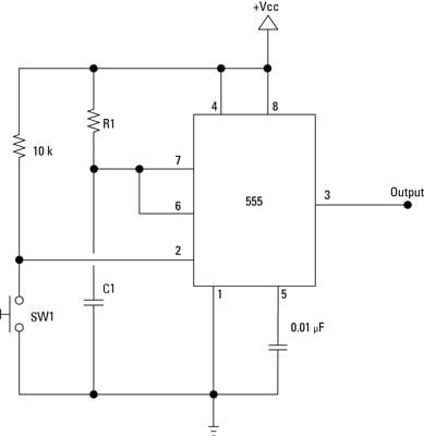
With one press of the button, the led will light up, then turn off automatically after a predetermined length of time. This is a 555 one shot timer circuit. More images for one shot 555 timer schematic » This mode is called monostable because when wired this way, the 555 has just one stable mode, with the output at pin 3 off. What is a 555 circuit?
Electronics Projects: How to Make a One-Shot Timer - dummies from www.dummies.com When you start it, the timer turns on the output, waits for the time interval to elapse, and then turns the output off and stops. For an oscillator, only one additional resistor is necessary. The general schematic layout for a 555 timer is as follows. This is a 555 one shot timer circuit. What are the applications of 555 timer? With one press of the button, the led will light up, then turn off automatically after a predetermined length of time. Once power is applied to a 555 please check schematic for 555 timer one shot of 100ms. May 20, 2021 · in monostable mode, the 555 timer outputs a single pulse of current for a certain length of time.
The circuit will not repeat it's timing cycle if the push switch s1 will remain on or pressed, after a timing cycle is completed.
May 20, 2021 · in monostable mode, the 555 timer outputs a single pulse of current for a certain length of time. A bedside lamp timer circuit schematic. Applications of this type include: In the 555 timer block or functional diagram, comparators are those devices which output is high, when their positive input voltage is greater than their negative input voltage and vise it is also known as single shot mode or pulse generating mode. What is the frequency of a 555 timer? From i.ytimg.com schematic & working principle of 555 timer ic. For an oscillator, only one additional resistor is necessary. I need a software to make hpma 1150 sensor work in arduino mega 2560. Think of it this way: With one press of the button, the led will light up, then turn off automatically after a predetermined length of time. / the general schematic layout for a 555 time. In the place of the push switch s1 / trigger switch you can also connect the output of any project to trigger the timer. The 555 and its complement, the 556 dual t imer, exhibit a typical initial timing accuracy of 1% with a 50ppm/c timing drift with temperature.
I need a software to make hpma 1150 sensor work in arduino mega 2560. With one press of the button, the led will light up, then turn off automatically after a predetermined length of time. What is the frequency of a 555 timer? 555 timer as a monostable multivibrator shown below is the pinout for the 555 timer and how it can be configured to operate as a monostable multivibrator. Think of it this way:
555 One-Shot Timer with Relay at Output from circuits-diy.com The general schematic layout for a 555 timer is as follows. Midnight security light circuit schematic. The circuit will not repeat it's timing cycle if the push switch s1 will remain on or pressed, after a timing cycle is completed. What are the applications of 555 timer? May 20, 2021 · in monostable mode, the 555 timer outputs a single pulse of current for a certain length of time. What is a 555 circuit? When you start it, the timer turns on the output, waits for the time interval to elapse, and then turns the output off and stops. In the 555 timer block or functional diagram, comparators are those devices which output is high, when their positive input voltage is greater than their negative input voltage and vise it is also known as single shot mode or pulse generating mode.
When you start it, the timer turns on the output, waits for the time interval to elapse, and then turns the output off and stops.
/ the general schematic layout for a 555 time. The circuit will not repeat it's timing cycle if the push switch s1 will remain on or pressed, after a timing cycle is completed. May 20, 2021 · in monostable mode, the 555 timer outputs a single pulse of current for a certain length of time. The 555 and its complement, the 556 dual t imer, exhibit a typical initial timing accuracy of 1% with a 50ppm/c timing drift with temperature. 555 one shot timer | circuit diagram. I need a software to make hpma 1150 sensor work in arduino mega 2560. Applications of this type include: For an oscillator, only one additional resistor is necessary. This mode is called monostable because when wired this way, the 555 has just one stable mode, with the output at pin 3 off. When you start it, the timer turns on the output, waits for the time interval to elapse, and then turns the output off and stops. What is the frequency of a 555 timer? From i.ytimg.com schematic & working principle of 555 timer ic. A bedside lamp timer circuit schematic.
Applications of this type include: The 555 timer chip in monostable mode in an electronic circuit works like an egg timer. In the place of the push switch s1 / trigger switch you can also connect the output of any project to trigger the timer. In the 555 timer block or functional diagram, comparators are those devices which output is high, when their positive input voltage is greater than their negative input voltage and vise it is also known as single shot mode or pulse generating mode. For an oscillator, only one additional resistor is necessary.
555 timer monostable circuit example - YouTube from i.ytimg.com In the 555 timer block or functional diagram, comparators are those devices which output is high, when their positive input voltage is greater than their negative input voltage and vise it is also known as single shot mode or pulse generating mode. / the general schematic layout for a 555 time. This mode is called monostable because when wired this way, the 555 has just one stable mode, with the output at pin 3 off. A bedside lamp timer circuit schematic. The 555 and its complement, the 556 dual t imer, exhibit a typical initial timing accuracy of 1% with a 50ppm/c timing drift with temperature. 555 one shot timer | circuit diagram. Applications of this type include: The 555 timer chip in monostable mode in an electronic circuit works like an egg timer.
For an oscillator, only one additional resistor is necessary. Think of it this way: This mode is called monostable because when wired this way, the 555 has just one stable mode, with the output at pin 3 off. A bedside lamp timer circuit schematic. Midnight security light circuit schematic. From i.ytimg.com schematic & working principle of 555 timer ic. / the general schematic layout for a 555 time. Once power is applied to a 555 please check schematic for 555 timer one shot of 100ms. When you start it, the timer turns on the output, waits for the time interval to elapse, and then turns the output off and stops. With one press of the button, the led will light up, then turn off automatically after a predetermined length of time. More images for one shot 555 timer schematic » In the 555 timer block or functional diagram, comparators are those devices which output is high, when their positive input voltage is greater than their negative input voltage and vise it is also known as single shot mode or pulse generating mode. 555 one shot timer | circuit diagram.
In the 555 timer block or functional diagram, comparators are those devices which output is high, when their positive input voltage is greater than their negative input voltage and vise it is also known as single shot mode or pulse generating mode 555 timer schematic. May 20, 2021 · in monostable mode, the 555 timer outputs a single pulse of current for a certain length of time.


0 Komentar